
成像椭偏仪的基本原理:
Many real samples are inhomogeneous due to grain boundaries, surface roughness, or textures. These surface features have a strong impact on the reflectivity properties of the sample. Two length scales have to be distinguished. Imhomogeneities below 1 micrometer cannot be resolved by Imaging ellipsometry, instead they may cause a depolarization of the reflected light. |
 |
Inhomogenities exceeding 1 micrometer are best described by an incoherent superposition of the individual rays of each homogeneous patch of the reflecting surface. The lateral inhomogeneity of the sample is transformed in the state of polarization of the reflected light. With the aid of proper imaging optics an ellipsometric image is formed which resemble the high vertical resolution of conventional ellipsometry for each homogeneous patch of the surface. The lateral resolution is on the order of 1-2 micrometer and is given by the numerical aperture of the objective.
Imaging ellipsometry combines the high vertical resolution of ellipsometry in the Angstroem range with the lateral resolution of conventional light microscopy (Micrometer). The constrast giving mechanism is the change in the state of polarization upon reflection. Imaging ellipsometry is an excellent tool to semi quantitatively assess surface layer and to visualize surface morphologies.
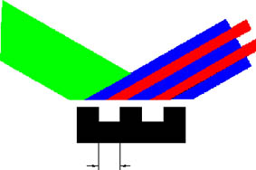
Imaging ellipsometry requires the image formation under an oblique angle of incidence. This imposes a specific problem. Depending on the angle of incidence, and the numerical aperture of the lens system, only a limited region of the illuminated part of the sample is in focus. This region is of the order of 5-50 Micrometer depending on the properties of the lens system. This problem is illustrated in the following Figure using a high magnifying lens system. |
 |
|
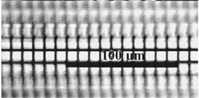
The stripe in the center of the image is in focus and towards the edges the image is blurred. This sample consists of a photo chemically patterned monolayer. The size of a bar is 1.9 micrometer the mesh size is 10 micrometer and imaging was performed at 53 degrees. The difference in height between dark and bright region is 0.7 nm. Obviously imaging at an oblique angle of incidence faces a severe limitation which is especially pronounced at higher magnifications. The area in focus decreases with the magnification.
|
|
 公司新闻
公司新闻

